Wednesday, February 22, 2012

Arkitypo: A Study of Design and 3D Printing

Today's blog is by Jon Fidler, digital artist, who created and fabricated 26 3D letters for a collaboration project called 'Architypo' with Ravensbourne, UK-based digital media university, and Johnson Banks.

Here at Ravenbourne, a London-based digital media university, we have just completed a collaboration project with London-based design studio Johnson Banks, setting about to create an 'alphabet of alphabets' and 3D print a complete set of 3D letters, each showcasing the character and history of a particular typeface.The project came about to develop a means of testing and showcasing our in-house 3D prototyping technology. For each of the letters 'A' through 'Z,' the designers selected a typeface beginning with that character, which is used in the sculptural work. Each piece furthermore encapsulates a bit of the history of the typeface:

The 'J' adopts the form of a metro system map, because its fontface 'johnston' was originally designed for the London underground; the 'C' is composed of 'courier,' used in 1950s typewriters, and thus is composed of an assemblage of typewriter keys.

'Arkitypo' took over six months to complete. Johnson Banks first researched each letter and then developed drawings, maquettes, and simple 3D renders before transferring the imagery. Ideas came to us at Ravensbourne where we utilised our 3D expertise and further developed the 3D models, collaborating virtually with Johnson Banks before beginning the first test prints. For the creation of the letters, me and my student, Jason Taylor, used a combination of software, including Solidworks, Rhino, Autocad and 3Ds Max to obtain the required results, and in some cases the letters took days to model.

Due to the existence of over 26 letters, we required a lot of prototyping to be carried out, in order to visually analyse what the designs looked like. For this, our ZPrinter 450 stepped up to the plate and, within a couple of hours, allowed us to print scaled versions of the letters to gain a perspective on their appearance. Then, we quickly edited designs if needed and quickly printed again to check the results. We used the printer to print some of the final letters which included A,D,E,F,H,I,L,N,O,Q,R,S,V,W,X, and Z. They can be seen below alongside the description. 'O' was a great example of where our ZPrinter was great! Using other machines, the software could not handle the complexity of the object, but we were able to open it up straight away in ZPrint software and print immediately. Because ZPrinters do not use physical support structures, we saved a lot of time processing the models. We then used all of the data created for the models to create the visulisations that can be see in the video: http://www.youtube.com/watch?v=8rGUU_B78mo&list=UUovfe8uBIStUFPjdWmVAuQw&index=1&feature=plcp

The complete alphabet, as well as some of the in-process renders are shown below:
The 'A' is composed of the typeface 'akzidenz grotesk' (1896). Among the first sans serif typefaces to be widely used, the design was part of a family of early san-serifs called 'grotesques.'

The 'B' is composed of the typeface 'bodoni' (1798), modeled after 'baskerville,' but exaggerated in its weight, with heavier thick lines and thinner thin ones. The Johnson Banks sculpture highlights this history with a 'bodoni' 'B' that traces its origin to its 'baskerville' form.
The 'C' is composed of the typeface 'courier' (1955), originally commissioned for 1950s IBM typewriters. Johnson Banks designed their model out of typewriter keys, referencing the old days of manual processing and jammed machinery.
The 'D' is composed of 'DIN 1451,' the typeface selected in 1936 as the standard for German engineering and civil service projects.
The 'E' is composed of 'engravers' (1899), designed for metal engraving.
The 'F' is composed of the blackletter typeface 'fraktur,' modeled after antique carolingian minuscule and other handwritten designs in order to provide a standard typeface for a series of books by Holy Roman Emperor Maximilian I. 'Fraktur' became the predominant style for the following centuries, until the 20th century, where it was ultimately banned by the Nazis in 1941. Here, Johnson Banks' design alludes to the typeface's close association with bookmaking.
The 'G' is composed of 'gill sans' (1933). Eric Gill, designer of the the typeface, is quoted as saying, 'a pair of spectacles is rather like a ‘g;’ I will make a ‘G’ rather like a pair of spectacles;' thus providing the reference point for the Johnson Banks model.
The 'H' is composed of 'helvetica' (originally 'neue haas grotesk', 1957; renamed in 1960). Latin for 'Switzerland,' the typeface became associated with both Swiss design and modernist industry and graphic design in general. The Johnson Banks sculpture assembles together the logos of some of the many corporations that use helvetica for their brand.
The 'I' uses 'industria,' originally designed by Neville Brody in 1984 for 'The Face' magazine.
The 'J' is composed of 'johnston' (1916), created for the London underground transit system, referenced by the Johnson Banks model.
The 'K' is composed of 'kabel' (1927), named in honour of the then newly-completed transatlantic telephone cable, which is the form utilized by Johnson Banks for the sculpture.
The 'L' is composed of 'lubalin graph.' The typeface was among the first slab serif alphabets for the phototypesetting industry.
The 'M' is based upon the 'machine' ITC typeface, often associated with industry, and thus already the influence behind the mechanical cogs used here to compose the letter.
The 'N' is created from the 'new alphabet' typeface (1967), a minimalist experimental font based on clean lines and precise angles.
The 'O' is composed of 'OCR-A,' whose strange characters filled the need for a font recognizable by both humans and the simple optical character recognition systems of early computers.
The 'P' is an assemblage of letters in the typeface 'perpetua' (1929). 'Here,' the designers of Johnson Banks explain, 'It is set to perpetuate in an endless möbius strip of uppercase letters.'
The 'Q' is composed of the typeface 'quadrate' (2002), which appears even in 2D to have a 3-dimensional element. As a result, Johnson Banks sought to produce what the real 3D letter 'could have been.'
The 'R' utilizes 'retina' (2002), Johnson Banks explains: 'At large sizes ['retina'] seems to feature crude ‘notches’ cut into the letterforms, but these are there to compensate for the way blobs of ink blur type at tiny sizes.'
The 'S' is composed of 'serifa' (1966), a serifed adaptation of 'univers.' In reference of this history, here the letterform appears to launch from a 'U' sculpture in 'univers.'
The 'T' is composed of 'trajan' (1989), a contemporary adaptation of the Roman capitals engraved on Trajan's column in Rome. The historical monument itself can be climbed via an internal spiral staircase, to which the Johnson Banks 'T' sculpture makes reference.
The 'U' is stylized in 'univers' (1957), now one of the world's most ubiquitous typefaces.
The 'V' is composed of 'verdana' (1996), designed for screen printing and bundled with early Windows software.
The 'W' utilizes the typeface 'wilhelm klingspor gotisch,' a blackletter design that draws from the curves of calligraphy, referenced in the Johnson Banks piece.
The 'X' is composed of 'xheighter' (1999), a tall, condensed sans serif whose form becomes emphasized in the skyscraper-like sculpture here.
The 'Y' features the typeface 'DFP yuan.' In addition to serving as the name for the country's currency, 'yuan' in Chinese literally means 'a round object' or 'round coin'. Here, intersecting '¥' symbols 'create an endless circle of chinese money.'
The 'Z' is composed of the 'zig zag' art deco-style typeface, here interlocked into a zig-zagging puzzlelike form.

Project Info:
Design: Johnson Banks
Client: ravensbourne
3D imaging and prototyping: Jon Fidler and Jason Taylor
Photography: Andy Morgan
Project client: Jill Hogan
Project advisor: Ben Caspersz

Wednesday, February 15, 2012

3D Printing for Full-Scale Design Studies

Today’s guest blog comes from Brian Spangler, Designer, Payette Associates, Boston, MA

As three-dimensional printing (3DP) technology increasingly embeds itself within the architectural practice as a viable representational technique, architects and designers must reconnoiter around the ideas and strategies that initially spawned the technology. Whereas 3DP’s current influence on the architectural design scene seems to be most characterized by the production of monolithic, mono-material, massing components, its success and influence originated on the engineering platform via the ability to produce accurate, complex geometrical prototypical, full-scale components.

Most significant to the architectural designer in the articulation of a physical study model is the ability to produce artifacts that facilitate and direct to the iterative design process. A primary catalyst for the success of this process requires dexterity and efficiency in the fabrication process itself. As designs are quickly modified and manipulated to fulfill evolving design intent, the fabrication process must efficiently anticipate and transform to accurately articulate new design ideals.

By deploying a scale shift likened to the prototypical roots of 3DP technology, the images below document a series of full-scale design studies investigating terra cotta rain screen cladding profiles. Of primary importance to the design team was the ability for the models to clearly convey the legibility of the profile from various distances and perspectives. Secondarily, the models proved useful in the comprehension of lighting consequences between the profiles. The combined curvilinear and faceted nature of the profiles clearly emphasizes the necessity of the digital fabrication process.  Most importantly, the full-size scale of the models in conjunction with the limited scope of the investigation allow the fabrication process to efficiently inform the decision making process. Two-dimensional, digitally documented profiles were easily and quickly manipulated to generate simple digital extrusions, thereby keeping pace with design changes.

Scale is here at the crux of the success; clients and designers alike are drawn to and impressed by the resolution and mastered comprehension of a seemingly insignificant aspect of the design, articulated in a clear and beautiful way.

 3D-printed prototype used in a series of terra-cotta profile design studies.


 3D-printed prototype used in a series of terra-cotta profile design studies.


 Vignette of 3D-printed prototype used in a series of terra-cotta  profile design studies.


Sample of terra cotta (left) with multiple 3D-printed prototypes (right) used to study terra cotta profiles.


Copyright Payette, Images by Brian Spangler

Wednesday, February 8, 2012

Powder vs. Plastic … Redux

When we first started writing in this space almost two years ago, one topic we covered was ‘Plaster vs. Plastic’ in 3D printing. Now that ZPrinters are part of a broader 3D Systems content-to-print solution portfolio, it seems like a good time to revisit this topic.
Previously I wrote …"In my travels around the world to various architectural firms, I occasionally see plastic models on display mixed among the wood, chipboard, and Plexiglas models in lobby exhibits. When I ask why that material was chosen, I get a variety of responses. Some say that their service bureau had an SLS or SLA machine, so this is what they delivered. Others say that clients perceive the plastic models to be more durable for long term display. "

While architects are happy to pass on their costs to the client for a one-time presentation model, most agree that there is no substitute for inexpensive, fast turnaround composite material (gypsum-based “plaster”) models during the early conceptual design and design development process. These are the times during the project when designers want immediate feedback and designs change quickly. How does your firm incorporate physical models into their design process, and what materials are preferred and why?

Two years later, we find that ZPrinters (powder and binder technology) are still the preferred tool for low-cost, fast-turnaround concept design models, such as this urban study model from Pelli Clarke Pelli below.
Having said that, we still see demand for fine detail, sharp edges, and smooth surfaces during later design development.
These features are also desired for final presentation models, and designers are willing to pay more (in time and materials) to get what they want, especially if they can bill their clients for models.
Model courtesy of Fonco Fabrication and Design
In a nutshell, AEC users typically want 3D printers capable of building big white models with fine detail and smooth surfaces. Color can be useful in later design stages. Users also want easy-to-use printers with reasonable operation costs.

Powder or plastic? Sometimes you need both!

http://www.zcorp.com/en/Solutions/Architecture/spage.aspx

Wednesday, February 1, 2012

How to Create Structural Forms with 3D Printing: PEGASUS Bridge

Today’s guest blog comes from Luca Frattari, AEC business development manager at Altair Engineering.

How is possible to create this Structural Form?

It’s hard to find the correct definition; certainly it’s very difficult to describe the essence of Structural Form, because it is totally influenced by two such precise concepts -- Structure and Form. Interesting examples might be represented by the study of Greek architecture, in which Structure and Form were strictly connected. It is possible to say that Greek Structural Form stems from mathematical rules and have produced a kind of beauty when the rules were used in Architecture. Technology has shown how much the form of an object is influenced by its structure and how much the structure of the same object is influenced by the form of its fundamental parts. Thinking about a crystal of snow, the borderline between structure and form seems to be very thin; it almost disappears.

The main aim of the PEGASUS bridge project was to create a Structural Form exploiting the potential of numerical analysis with new concept design tools and rapid prototyping systems. The proposed bridge has been designed to cross Big Beaver Road (Troy, Michigan, USA). The project has been focused mainly on the development of an organic-like structure that satisfies structural and aesthetic criteria exploiting the application of Altair’s technology in Architecture creating a strong interaction between CAE, CAD and RP systems. Altair’s solidThinking Inspire, Optistruct and HyperMesh have been used to define the support structure (50 meters long) and its shelter.

The developed methodology is based on five easy steps:

(1) Creation of a standard steel-deck.
(2) Finding the architectural Structural Form of columns and shelter by using a topology optimization procedure.
(3) Skin (columns) and Shelter re-design.
(4) Improve skin by using size optimization to reduce the thickness of the steel components saving material without compromising on the structural performance.
(5) Verification of the entire structure subjected to standard design actions.

The creation of a 3D printed model has amplified the perception of the bridge in a real environment, allowing a complete evaluation of the streamlines. Complex structures such as the results of a form-finding procedure, parametric and generative approaches require, as condition sine qua non, a further step after the virtual visualization to be totally perceived in the space. A ZPrinter model has brought PEGASUS to life; I like to say it has given him wings. The main reason is because Structural Forms like PEGASUS need two kinds of restitutions to be completely appreciated: virtual 3D and real 3D visualizations. It is unbelievable how much attention a 3D printed model can capture simply standing on a desk during an architectural exhibition.


http://www.zcorp.com/en/Solutions/Architecture/spage.aspx

Wednesday, January 25, 2012

A 3D Printed Model is Worth a Thousand Words

Today's blog is by Julie Reece.


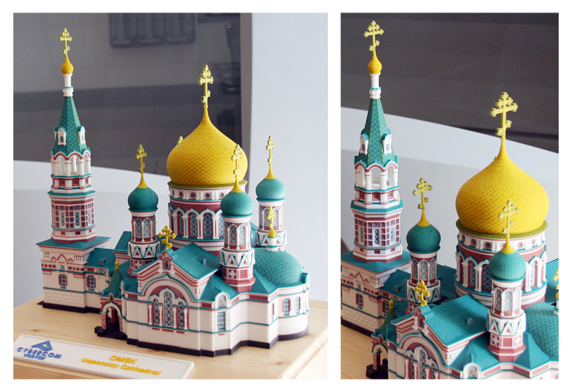
Every month, we feature a “part of the month” that our customers and dealers can download and print on their own ZPrinters. This month’s part was created by our Russian channel partner, Cybercom.

OMSK Dormition Cathedral
CYBERCOM
Modeled by: Nikita Istratiy
(using 3DS Max)
Printed on ZPrinter 650
Let me stress that this model was not painted. It was printed in full color on a ZPrinter 3D printer. I can talk at length about how the ZPrinter creates far more accurate architectural models than handcrafting models, for a fraction of the time and price, but I believe in the old adage, “a picture is worth a thousand words.” Imagine the possibilities – you can print several of these models at once and give them to the client, zoning board, construction crew, and community groups. The amount of information conveyed in the 3D printed model is infinitely more than a 2D rendering, which results in faster approvals. You can even print several different versions of the design at one time in order to steer the client toward your desired design – the possibilities are mindboggling. Ultimately, what it means for you are better designs and more business.

If you haven’t yet adopted a 3D printer in your architectural firm, I am interested in learning why.

http://www.zcorp.com/en/Solutions/Architecture/spage.aspx

Wednesday, January 18, 2012

Printing 3D Building Components

Normally in this space, we write about design process improvement using 3D physical scale models for better collaboration and communication.  This week, we will touch on some innovative research being done with 3D printing technology at U. Cal – Berkeley.  Prof. Ronald Rael has developed a new process that enables the printing of production-ready building components. Following is his guest blog.
Printing unique, one-of-a-kind building components that are generated quickly and economically to produce large scale -objects, is the current research of Ronald Rael, Assistant Professor of Architecture at the University of California, Berkeley and founding partner of Rael San Fratello Architects. This year, he has developed a cement-based polymer and a new process that, for the first time, employs conventional rapid prototyping hardware to produce strong and durable building components that cost far less than conventional rapid prototyping materials—up to 90% less than comparable printing materials. The material can also reach strengths of up to 4,700psi in compression, which is comparable to the strength of concrete. This advancement in material output from digital modeling software ushers in a new era in building materials, and a new synthesis of design and production.

The SeatSlug, a biomorphic interpretation of a bench, demonstrates how this new digital output process generates end-product structural building components directly from 3D software models. The design is inspired by flabellina goddardi, the newest species of sea slugs discovered in California in 2010, and by the infinite tessellations of Japanese karakusa patterns. It is constructed of 230 unique rapid-manufactured components. The sinuous form, subtle translucency and glossy finish engage viewers with a memorable aesthetic experience—a tactile personal encounter with a technological breakthrough.

Wednesday, January 4, 2012

Create More … Design Process Improvement in 2012

Two weeks ago, I summarized preliminary 2011 results and commented on industry trends for 3D printing in the AEC community.  Final results exceeded expectations – ZPrinter business in the AEC vertical market grew more than 30% in units and 50% in revenues year-over-year.  Now, let’s take a peek into the crystal ball for 2012.

Based on a stronger than expected finish in 2011, I will go out on a limb to predict that this year will see many more AEC firms diving into 3D printing to improve/accelerate their design process.  This will happen in two ways. First, those firms that are bouncing back from the recession, and have always wanted their own 3D printer, will finally make the investment they could not justify during the past two years.  What evidence do I have for this prediction?  Z Corp. had a 40% increase in new AEC customers last year compared to the prior year.  These new users were not the typical ‘starchitects’ that adopted 3D printing in the past, but rather small-to-medium sized firms that are trying to differentiate themselves from regional and national competitors.  Half of these new customers are from North America, which should lead the growth in 2012.

The second way that AEC firms will invest in 3D printing will be through service bureaus on a project-by-project basis.  There are service bureaus all over the world that specialize in architectural models.  Savvy designers will use their services to print models which will help them collaborate on project teams.  Once the clients, principals, and other project participants see the value of 3D printed models during the design process, these firms will move into the first category described above.

Other thoughts for 2012 …

The first release of the new AMF 3D printing export standard http://amf.wikispaces.com/ should have some positive impact for 3D printing as a whole, but will not be really felt until the content creators (i.e. the CAD/BIM suppliers) add this feature to their design software products.  Many developers are already finished with their 2012 feature enhancements, so we may not see the AMF export option appear in popular design software until calendar 2013.  For those nimble software developers who support AMF early on, their users will benefit by having color, texture, and material properties exported along with their design geometry.

Bigger is better – the trend toward larger build sizes will continue in 2012 as more users migrate toward bigger 3D printers.  In 2011, more than half of all ZPrinters shipped to AEC customers were ZPrinter model 650 [15x10x8 inches build size].  The press likes to talk about low-end inexpensive printers, but the fact is that real production work is trending in the other direction.  Larger build size has two benefits:  scale model size can be increased without splitting pieces; and more design iterations can be printed in one job which increases throughput and helps enable innovation.

More “shelf space” – with Z Corp now part of 3D Systems, the reseller community has the potential to grow dramatically.  This means that more companies will be serviced by more local resellers and 3D printing professionals.  Those of us in the business are always amazed when we go to industry events and talk to people who have never seen a 3D printer.  The fact is that even though this type of technology has been around for 20+ years, many folks (especially in AEC) are just hearing about it.  Having more authorized representatives out in the trenches will move 3D printing from the aisle shelves to the end displays.

Wishing all of our readers a happy, healthy and prosperous New Year!

http://www.zcorp.com/en/Solutions/Architecture/spage.aspx