Wednesday, December 29, 2010

December’s Top 10 Favorite AEC 3D Printed Models

Guest blog by Julie Reece, Z Corp. Director of Marketing Communications.
Throughout the day I am fortunate enough to see a wide variety of ZPrinted models for a number of applications.  I am especially fond of AEC models because of the forms, intricate details and texture maps.  I decided to compile my top 10 favorite AEC ZPrinted models for December. See what you think...
1. St. Basil’s Cathedral (this is my favorite because of the vibrant color and textures that were 3D printed right out of a ZPrinter; this model is sitting on my desk.):

2. Boston Society of Architecture Building, courtesy of Munson3d.com (the textures on the façade and roof are incredible, and if you look closely at the first floor windows, you can see the full color, 3D printed images of the window displays– amazing!):

3. MIT Building (the bright white color of this model, combined with the textures, fine wall thicknesses and large size of the model itself, make this one of my favorites):

4. Bentley MicroStation plant model courtesy of Shinryo International and Team-S (the intricate web of pipes was 3D printed as one model in a single build):

5. Manhattan Cityscape (this is just downright impressive):

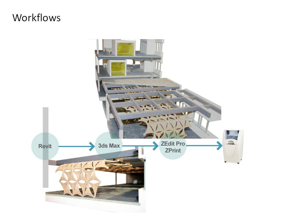
6. Detailed design study of a building (just look at the thin railings and the textures, which were 3D printed – not painted!):

7. Cutaway of a historic theatre (chosen for the incredible ZPrinted detail; check out the staircases on the inside of the model):

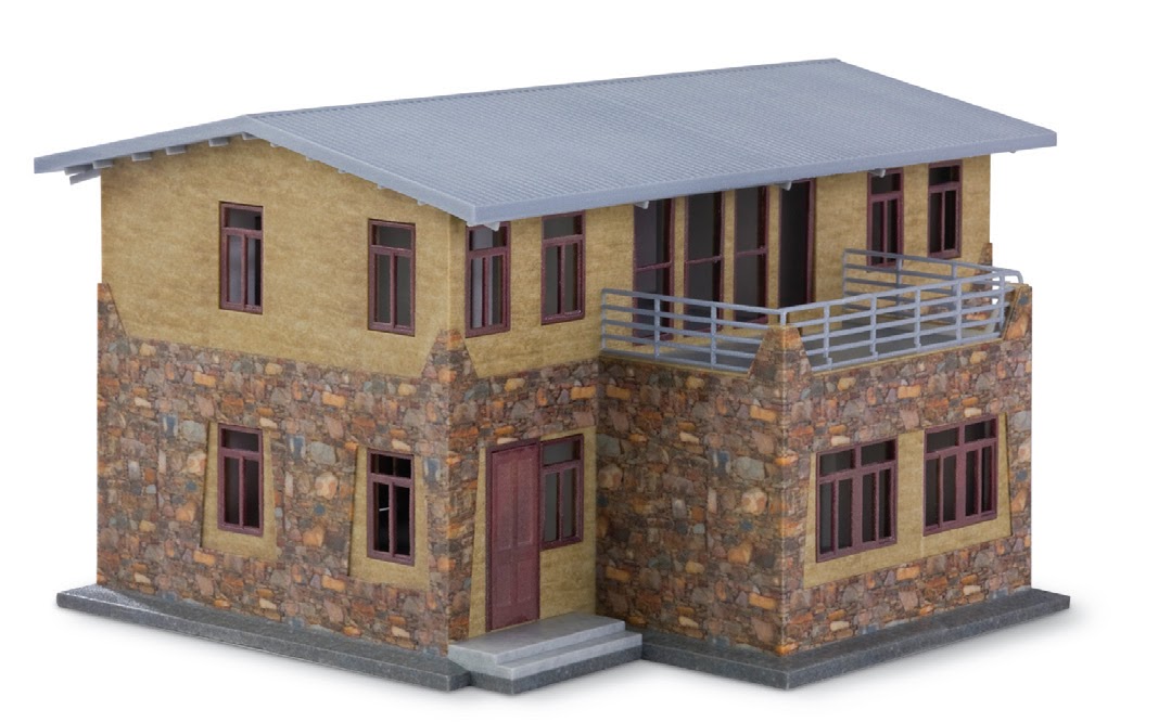
8. Courtesy of The Realization Group (this model is one of my favorites because of its large size, intricate detail, thin walls, and 3D printed roof shingles):

9. Courtesy of The Realization Group (this one gets points because it’s lit from the inside to demonstrate what the complex will look like at night when lights are on):

10. Courtesy of Ralf Lindemann (this model is impressive because the simplicity of white on black and its organic design):


Ok, 11. I couldn’t resist! (the curved lines of this ZPrinted model give the impression that it’s swaying in the breeze):


Which of these 3D printed models is your favorite? Do you have photos of ZPrinted AEC models that you’d like to see in our list of January favorites? Send them to jreece@zcorp.com.
http://www.zcorp.com  

Wednesday, December 22, 2010

ZPrint Helps Vision Impaired Couple Visualize New Home

How many of you watch the ABC television series Extreme Home Makeover?

An architectural scale model built by Z Corp. customer Moody Nolan of Columbus, Ohio, and supported by Z Corp. channel partner 3DP Technology, appeared on the December 5th edition of the popular TV show. A visually impaired couple devoted to helping the local community received a home makeover, complete with technologies that help people with disabilities. Since the couple could not see their new home, a ZPrinted model was provided to them so they could feel their home in order to get a sense of what it looked like.


The full episode can be seen in the following link: http://abc.go.com/watch/extreme-makeover-home-edition/SH559052/VD55100979/the-anderson-family. Watch for the scene after they move the bus to expose the family’s new home.

A video showing how the model was made appears in the following link: http://www.youtube.com/watch?v=Az-kXbLd0mg.

Note that Moody Nolan uses a ZPrinter 650 for maximum build size, and with zp150 composite material, they are able to infiltrate their ZPrints with salt water spray. Like many architects, Moody Nolan wants to produce the whitest models at the lowest costs in the fastest time. The ZPrinter 650 with zp150 enables them to do so.

For more info on the zp150 composite material, visit http://www.zcorp.com/en/Products/3D-Printers/Material-Options/spage.aspx.

http://www.zcorp.com

Wednesday, December 15, 2010

Autodesk University 2010 – Part II

Last week, I blogged about AU 2010 and wrote about the Product Clinic virtual class and the Autodesk technology presentations. This week, let’s talk about the Exhibit Hall.

On the Z Corp. stand, we showed our ZPrinter 450, ZScanner 700, and ZBuilder Ultra solutions with several part models from the printer and rapid prototyping systems. As usual, visitors to the booth were impressed with the detail and color quality of the ZPrints. This year, several Autodesk users from the manufacturing and product design space were equally intrigued by the resolution and smoothness of the ZBuilder Ultra plastic prototype parts.

In the Autodesk exhibit space, the Tesla Motors full-size electric car took center stage, but there were a couple of interesting 3D printed scale models on display as well. Let’s start with the Austrian pavilion at the Shanghai World Expo. This futuristic building was designed by SPAN Architects and scale models (approximately 24 inches x 20 inches) were completed with traditional subtractive metal manufacturing, plastic, and plaster-based (Z Corp.) systems. It was interesting to see the differences and the pros/cons for each model. The metal model was painted in a shiny gloss white and quite smooth, but likely cost a bundle to manufacture.


The plastic model (by another manufacturer) was printed as one piece in orange plastic and contour stair-stepping is quite visible, leading me to question, "Why didn't somebody sand this model?"

The Z Corp. model was printed in four separate pieces on a ZPrinter 650 to get the desired scale with the added benefit of being able to see inside the structure.

The Autodesk Exhibit Manager, Matt Tierney, was quite pleased with the overall quality and smooth look and feel of the model.

A few feet away from the World Expo display, there was an exhibigt featuring the work of Autodesk CEO, Carl Bass, a noted furniture-making enthusiast.


Using the ZPrinter 450 in the Autodesk San Francisco Customer Briefing Center, Bass had several 3D prints created with different surface finishes and textures.  One was speckled granite adnd others were wood grain.  Ultimately, Bass chose black granite for his home garden piece.


http://www.zcorp.com

Wednesday, December 8, 2010

Autodesk University 2010 – part I

Autodesk University (AU) took place last week in Las Vegas. Attendance (7000+) was up this year after a two-year decline, and the energy level was palpable. I felt it in the exhibit hall and in between the classroom sessions. While at AU, I delivered a Product Clinic in the form of a virtual class; the clinic was entitled “The Emergence of 3D Printing in AEC” and the content was based on the AIA Continuing Education course of a similar title. Attendees were able to see/hear the webcast and then ask questions in a live chat window. The AU folks plan to post these virtual classes for those who could not attend during the clinic time slots.

Aside from my “virtual speaking” class, here are some AU2010 observations - part I (part II next week):

In the opening general session, Autodesk CEO Carl Bass introduced six presenters from multiple industries (building, infrastructure, manufacturing, and entertainment) who described their recent projects around the theme of “making an impact.” The talks included interesting projects from Tesla Motors (Autodesk Alias styled electric car driven on stage), Project H Design (Autodesk AEC software presumably used), Bespoke Innovations (custom-designed and 3D-printed prosthetic devices), and the digital studio that made the new TRON movie (Autodesk Media & Entertainment software). Autodesk CTO Jeff Kowalski talked about the cloud or “infinite computing” and how it will change the way people design and simulate. The entire General Session is available here - http://au.autodesk.com/?nd=keynote

The building industry keynote was all about the use of BIM “assets” for downstream applications such as MEP system design, structural design/analysis, building performance analysis, construction scheduling, and efficient facility maintenance and operation. There was also a quick look at Project Vasari. Here is the description from Autodesk Labs web page …

Autodesk® Project Vasari is an easy-to-use, expressive design tool for creating building concepts. Vasari goes further, with integrated analysis for energy and carbon, providing design insight where the most important design decisions are made. And, when it’s time to move the design to production, simply bring your Vasari design data into the Autodesk® Revit® platform for BIM, ensuring clear execution of design intent.

Project Vasari is focused on conceptual building design using both geometric and parametric modeling. It supports performance-based design via integrated energy modeling and analysis features. This new technology preview is now available as a free download and trial on Autodesk Labs.

It will be interesting to see if this software can stop the Google SketchUp and Rhino momentum in the AEC market, and how Autodesk will choose to package and market this new conceptual design tool. So far, 80,000 downloads have been reported. You may recall an earlier guest blog in this space by Microsol’s Dolly Haardt showing how a conceptual massing model in Revit can be exported for 3D printing. As far as I understand, these are the design tools which are in Project Vasari.

More on AU2010 next week!

http://www.zcorp.com

Wednesday, December 1, 2010

Six Steps to Assess the True Cost of a 3D Printing System

Guest post by Mark Cook, Z Corp.'s VP of Research and Development.

There’s been a lot of hype over the past year about low-cost 3D printers. All of the rapid prototyping (additive manufacturing) companies have either introduced low-priced systems to the market or lowered the price of existing systems and promote how they are making the technology more accessible to designers, engineers and even the hobbyist. Editors, industry analysts and even the New York Times have jumped on this trend which seems to be the focus of nearly every article and report.

But what is a low-cost 3D printer? When people talk about low cost, they seem to refer only to the purchase price of the 3D printer. Sometimes machines that are billed as low cost are actually much more expensive than most other machines when all variable costs are factored into the equation. We’ve had customers tell us that they purchased another system because of the low initial purchase price of the printer itself, only to quickly discover that they couldn’t afford to keep the system operating. It became an expensive paper weight.

So, how can you cut through the hype and determine the real cost of a 3D printer? Here are six easy steps.

First, let me provide a disclaimer that I’m only referencing industrial- or professional-quality 3D printers. Industry experts seem to universally agree that open source systems that have been receiving quite a bit of publicity recently are not suitable for professional use from a quality, accuracy, throughput or speed standpoint.

1. Yes, affordability starts with a low-priced machine. But look beyond the price of the machine itself. Check to see if the system requires expensive lasers, complex thermal controls or special facility requirements. All of these items can add thousands of dollars onto the price of a machine.

2. How expensive is the build material? Find out how much build material is included in the purchase price of the system. Be sure to base this cost on volume rather than weight (i.e.; how many prototypes will that amount produce?). Then learn the on-going replacement cost of the material.

3. What about waste? Is all of the unused build material from a build completely recycled for future builds and therefore unwasted? If not, make sure you factor the cost of the wasted material into your cost calculator. And, does the system require you to build supports? Some systems require you to build supports, others don’t. Building supports requires expensive build material that can really add up over time, so be sure you factor this ongoing cost into your estimate.

4. What about the cost of post-processing? All prototyping systems require some sort of post-processing. Check to see if you must purchase additional equipment, chemicals, ventilation and special hazardous waste handling and disposal in order to post-process parts. Compare those systems with systems that provide you with the low-cost option to cure parts with tap water and Epsom salt.

5. Assess maintenance costs. Some systems use standard, off-the-shelf inkjet printing technology and a modular design in order to make component replacement quick, easy and cost efficient.

6. Considering all of these variable costs, estimate the total expense per finished model.

Example:
Total cost for Z Corp.'s finished ZPrinted models runs about $2 - $3 USD per cubic in ($0.12-$0.18 USD per cubic cm).  A 4.0 cubic in (66 cubic cm) model like the one below costs less than $20 USD to produce.


If low-cost 3D printing is important to you, “Buyer beware.”

http://www.zcorp.com

Wednesday, November 24, 2010

BuildBoston 2010 and AIA CES Workshop

Last week, I delivered a workshop talk at the Build Boston conference.

The topic was, what else, 3D Printing in AEC. The 90-minute workshop was structured around the AIA CES approved course by the same name. I was assisted by David Munson of munson3d, an industry consultant with deep experience in architectural design and visualization software and 3D printing.

The audience included a variety of architects ranging from a college senior thinking about using 3D printing for his thesis project to entry level designers to experienced architects/firm principals to retired architects wanting to learn more about new technology in their field. The most notable thing about this workshop is that questions from the audience started on my third slide, and they kept coming from different attendees such that I began to worry about covering all the content in the time allotted. This is a good problem to have. Usually in these AIA CES presentations, folks politely listen, check their watches periodically, fill out the questionnaire to get their AIA credits, and head out quickly to beat the lunch lines. This time, there was genuine interest in the subject matter as evidenced by the intelligent questions, and I could almost hear the gears turning in the minds of these architects as they thought about how to incorporate 3D printing in their design process. A few people stayed afterward to ask more questions – always a good sign!

Dave Munson did a terrific job in describing the various workflow options from CAD to 3D print along with several example projects he has worked on. By polling the audience in advance, we knew to focus on particular design-to-print workflows such as AutoCAD, Revit, SketchUp, and 3dsMax. We had about 15 models on display to help us illustrate the technology, and we passed these models around the room so that attendees could get a closer look.

Following are several workflows, courtesy of David Munson, Munson3D:


For readers in other parts of the US, contact your local Z Corp. dealer to ask about delivering the AIA CES course at your firm. Readers outside the US can contact me for more information by replying to this blog.

Happy Thanksgiving!

http://www.zcorp.com

Wednesday, November 17, 2010

Interactive Fabrication - Modeling and 3D Printing From an iPad

Some of you may be familiar with the Association of Professional Model Makers (APMM). This organization is made up of industry professionals worldwide who specialize in making models of all types – architectural, manufacturing, medical, entertainment, etc. Recently, an APMM member came upon this cool technology which uses an iPad as an interface for sculptural modeling. The software is called Beautiful Modeler.

Beautiful Modeler is a software tool for gestural sculpting using a multi-touch controller such as an iPad. Each finger is used to control a single touch point in the model, with multiple layers working to build up 3D volume. Take a look at this video:

http://www.tuaw.com/2010/11/09/sculpt-a-3d-model-using-the-ipads-touchscreen-and-accelerometer/

The interactive fabrication tool has STL file export so that these gestural sculpting designs (or their negatives) can be printed.

Will this input device and associated software transform the way people design and fabricate? Maybe. Let’s take a look back in recent history. An argument can be made that the design tool itself can impact the creativity of the designer and the final look-and-feel of the design. For example, the use of Bentley’s GenerativeComponents software has impacted the skylines of Dubai, Almaty, and other cities. Take a look at the Gallery images. These are not the traditional geometries created with 2D or simple 3D design tools. Another example is the use of a haptic device with force-feedback for freeform design. By using a haptic device tied to voxel-based modeling software, designers can literally feel like they are carving clay. See the variety of applications on SensAble Technologies’ Website which would be difficult-to-impossible to model with traditional CAD tools -

What makes Beautiful Modeler intriguing is that the software source code is in the public domain. Technology adoption tends to accelerate when the cost is low. The use of an iPad is also very clever – why not leverage the Apple marketing machine?

I think that this technology might go somewhere. What do you think?

http://www.zcorp.com

Wednesday, November 10, 2010

3D Physical Modeling in the AEC Community

This past summer, we conducted a market survey which asked questions about the use of physical modeling in the building design process. The survey was sent to a rented list of architectural firms of all sizes across the US and Canada. Most of the respondents were employed at small firms, so the results are a bit skewed. Despite the small sample size, the answers were enlightening. Let’s look at the first question we asked and the results summary:
Frankly, I was surprised about the low usage of 3D tools in general, and alarmed about the infrequent use of 3D physical models. Remember, we didn’t ask about “3D prints” or “rapid prototypes” – we simply asked if 3D physical models were being used for their projects. Again, this result could be reflective on the state of the industry and the types of projects that architects have been doing during the recession. My guess is that most recent projects did not involve creative 3D multiple design concepts when simple 2D construction documents would suffice.

In a subsequent question we asked, “For those projects where physical models are created, please estimate the percentage use of each of the following 3D physical modeling techniques.” We offered choices which included laser cut materials and assembly, CNC materials/assembly, 3D printing, and handmade models crafted with cardboard, chipboard, foam, etc.

The primary response was … you guessed it – handmade cardboard/chipboard/foam models. These models were constructed mainly by junior designer/architects at lower pay scales. Using this approach is time-consuming and expensive, and results in models which may not reflect the architect’s design or show that design in the best possible light. With the right tools, such as a fast 3D printer with low-cost consumables, great looking 3D physical models can be made without the time and labor expense of doing it the old-fashioned way. And, these models can be used to more proactively engage clients and other stakeholders to accelerate design decisions and approvals.

I would love to hear your views on physical modeling in the design process!


http://www.zcorp.com  

Wednesday, November 3, 2010

3D Printing from Rhino

Last week, we wrote about alternative workflows from Revit to 3D printing. I ended the blog with this statement … Some use Rhino in their workflow, which has the added benefit of exporting a ZPR file directly into ZPrint.

Let’s dive into the Rhino workflow a bit deeper. For those of you who use Rhino, you know that the software offers several Export options. This is best illustrated with an example. Here is a model for an organic sports stadium, complete with surrounding site, provided by T-Splines of Provo, Utah.

With one menu pick, we can select the entire model for Export (note all the options):
About two-thirds of the way down the list, note the Z Corp. (.zpr) option. ZPR is a file format developed by Z Corp. which not only includes the polygon mesh geometry but also the color and texture information in the CAD model.

When we open the ZPR file directly in ZPrint, we see this (note the retention of color information):

This file was checked in ZEdit Pro to ensure a water-tight model, and then printed on a high def color ZPrinter® model 650. Here is a photo of the 3D printed model:
For reference, this model took about 5 hours to print with a material cost of approx $300.

Our experience with the Rhino ZPR export has been very positive. Please share your experience.

Wednesday, October 27, 2010

More on Revit export options for 3D Printing

Last week, Dolly Haardt discussed and showed us a video about the STL Export add-in tool for Revit. Good stuff!

A few months ago, on the LinkedIn group site called 3D Printing for Architects, there was some related discussion about the best methods to get Revit designs to 3D printing. Some alternatives to STL were presented as options. For example, Zvi Grinburg of CALIBER Engineering and Computers Ltd., a Z Corp. partner in Israel, posted this comment:

I don't want to spoil the STL party, but the most successful models we received and printed from Revit were those with in ACIS SAT format. I feel much more confident when the model is totally editable. Being able to edit the solid file - eliminates all the architectural typical surprises of thin walls, delicate features, non-touching objects and floating elements. It also enables for intelligent separation which can make a difference between a good and an awesome model. Most significantly, it gives a chance for proper model hollowing and draining, which can reduce a model cost from "out of question" to comfortable.

Now, I don't say that all models should be edited in CAD, but Revit is a good example of architectural CAD that can provide good solid data.

When we receive polygon files (VRML, STL, 3DS etc) we are at the mercy of the designer's ability to comprehend what a physical model is all about. At the alternative cost of numerous iterations, we take the time to review the model and make it ultimately and pleasantly printable.

FWIW, my tool for geometry editing is KeyCreator. This is a pure geometry free-form hybrid modeler (wireframe, surface, solid) that has great control and geometry management facilities and can edit almost everything as if it was natively created.

Matt Mondo from Impact 3D Models, a service bureau specializing in architectural models, posted:

I have to agree with Zvi. Many architects in our area are new to 3D printing and when we usually receive a direct export from Revit, we have the issues that Zvi mentions. It's great that there is an export tool, but it must come with the understanding that it is not a "one click" process where you have an instant 3D printable model; the customer needs to set up their focus (e.g exterior only, etc) before export.

I know that others prefer to take the digital model from Revit into 3dsMax to prepare models for 3D printing, especially when color and texture are desired (VRML export). Some use Rhino in their workflow, which has the added benefit of exporting a ZPR file directly into ZPrint. What is your preference?

http://www.zcorp.com

Wednesday, October 20, 2010

Model Transformation: Revit, Google Earth and 3D Printing

Today’s guest blog is from Dolly L. Haardt, LEED AP, Architectural BIM Specialist, Microsol Resources, New York City.  Microsol is an Authorized Reseller for Z Corporation. 
It’s amazing what you can do with a Revit project, from publishing it into Google Earth to printing a 3D model, the capabilities seem endless. Some of the most powerful aspects of Revit are the Add-Ins, which essentially are plug-ins to the software to expand its functionality. I’m going to walk you through the Globe Link and STL Add-In tools, so that you can familiarize yourself with how to publish a Revit mass into Google Earth and how to export an STL file to print a 3D model.

First let’s talk about Revit and Google Earth. For those of you that understand the basics of Revit, you know that Project Location is extremely important and can cause havoc down the road if ignored. The beauty of linking your model to Google Earth is that you can import the latitude and longitude of a particular location into your Revit Project. To start you need to make sure that you have the Globe Link Add-In tool; it can be downloaded at subscription.autodesk.com. This is a free tool if you are an Autodesk subscription customer. Once you download and install the Add-In, you will see the commands listed under the External Tools Menu. Then, locate your project in Google Earth and simply ‘Acquire’ the location in your Revit Site view. Once you mass out your design, confirm that you are in a 3D view and ‘Publish’ your model to Google Earth via the Add-In menu. It’s basically that simple. Here is a link to a video I created showing you the process.

Now let’s discuss Revit and 3D Printing. There is a free Add-In tool that you can get at labs.autodesk.com called STL Exporter for Revit Platform. This gives you the ability to take any Revit model and export it out to an STL format. The 2011 Autodesk tool has new features that the 2010 tool did not include, so it is well worth the upgrade. Similar to the Google Earth process, you will want to make sure that a 3D view is active before exporting. I do want to clarify one important point, similar to the process for photorealistic rendering, for 3D printing there is pre-processing work that needs to be done. Your model needs to conform to standards depending on the final output. For example, let’s say you want to bring this model into ZPrint, which is software provided by Z Corporation for printing on their various 3D printers, you will need to adhere to certain guidelines: a water tight model, no inverted surface normals, and minimum element thickness. Once you have gone through this process, you can bring the STL file into ZPrint and then check it in ZEdit Pro for any issues that may need repair. Once you get the ‘Congratulations’ dialog box you are ready to print. Here is a link to a video I created showing you the process.

Both the Globe Link and the STL Export tools are quick to install and master. With a little bit of guidance from my videos, I hope you have the opportunity to test out these latest features. I have found that showing clients their project in Google Earth and printing out 3D massing models helps communicate design concepts most successfully. Keep in mind that these are just a couple of the latest tools out there to enhance your workflow.

http://www.zcorp.com

Wednesday, October 13, 2010

Tools to Prepare Google SketchUp Designs for 3D Printing

Over the past few years of monitoring architectural practices, we are seeing more and more interest in 3D printing from Google SketchUp designs. We hear architects tell us that SketchUp is easy to use, especially in the early design stages where multiple iterations are needed to move a project forward.

This is good news and bad news for 3D printing. The good news is that 3D printing adds the most value to a design process by enabling the physical visualization of multiple concepts as early as possible. The bad news is that SketchUp behaves more like a rendering tool, not like a solid modeling system. With a rendering tool, designers must take more care in preparing their model for 3D printing to ensure a water-tight model. To be fair, we have seen enhancements in Google SketchUp v8 which begin to address the solid modeling issue.

In the meantime, a few experienced vendors have stepped in with tools to assist with preparing models for 3D printing. One supplier, LGM Model, has created a SketchUp plug-in called CADspan -  CADspan will resurface your SketchUp design and essentially shrink-wrap it to create a single water-tight model for 3D printing.

Another well-known vendor, Materialise, has formed a business unit called iMaterialise. They offer an i.materialise service which will 3D print your model. They also developed a Google SketchUp plugin to assists in the creation and 3D printing of architectural scale models. iMaterialise recently sponsored a design contest using this SketchUp plug-in module. You’ll find pictures of the winning designs here: http://picasaweb.google.com/i.materialise/IMaterialiseSketchUpContent#.

Has anybody heard of similar SketchUp tools? Please share your experiences.

http://www.zcorp.com

Wednesday, October 6, 2010

Timber House

Today's guest post is by Mark Cook, Z Corp. VP of Research and Development.

One of the things I love about working here at Z Corp. is when I am able to help someone discover the unique capabilities of 3D printing, specifically how ZPrinting can help solve real problems.

A few weeks back I ran into an old friend, during a wine tasting event at a local vineyard, who I had not seen in many years. As is often the case during these chance meetings, we both talked at length about what we had been up to over the past few years. The last time I saw him I must have just recently started my career at Z Corp. because he seemed to remember me telling him something about models. My friend is a local architect specializing in high-end custom homes.

Like many individual or small firm architects that have been around for a while, this guy hand draws most of his concepts and many of his detail drawings. His early design decision process involves sketching concepts, reviewing them with the customer, and re-sketching until they both agree on what is to be built. This is time consuming and at the end to the day there is always a risk that the sketch did not accurately represent the final building. How close the end product is to what is expected depends upon the quality of the sketches, as well as the customers’ ability to interpret them or to visualize the final building from the sketches.

Recently some of the younger architects working with my friend started using 3D software to turn early concepts into more realistic renderings in an effort to better communicate and make decisions at this early design stage. As luck would have it, they were in the midst of a project with a client where the husband was in the building profession and, because of his experience, could easily interpret drawings. The husband and wife were in disagreement about a particular detail - whether an entire wall in their new great room should be made of stone or just the section above the fireplace. The architect had rendered the room and shown them the renderings on the computer screen, but a decision had yet to be made.

I offered to take the 3D data from their software and print a model for their next client meeting on the following Thursday. I was able to export the 3D data, including texture map images for the wood, stone and other surfaces. I delivered the completed ¼” scale model in full color on Wednesday afternoon. My friend was amazed, his client was amazed, and I was very happy to help. The husband was finally convinced that his wife was right. Through a chance meeting at a local vineyard, I was able to help a friend solve a real issue by improving communication using Z Corp. 3D printing technology.

Click here and scroll to the bottom of the page to see a sampling of ZPrinted architectural models.

Wednesday, September 29, 2010

“Britain’s best architect”

I came across this article in Building Design recently “Gove waxes lyrical over Amanda Levete” by Elizabeth Hopkirk. The article describes how Britain’s Education Secretary, Michael Gove, called Amanda Levete “Britain’s best architect” during a ribbon-cutting ceremony at the Globe Academy in South London, which the firm designed. Gove went on to say, “So much care and attention and the work of Britain’s best architect has gone into providing you with the best possible building in which to spend the next few years.” He said everyone involved in the design had “shaped a building which is impressive on the outside and beautiful on the inside.”

Why did this article catch my attention? Amanda Levete Architects is a Z Corp. customer. They use a ZPrinter 450, multicolor 3D printer. 

It’s gratifying to know that Z Corp. technology is being used by the best architectural firms to quickly and cost effectively create the most innovative designs in an iterative manner, and then have those designs validated by such a prestigious, independent third party. But it also makes me wonder why some architectural firms have not yet adopted 3D printing. If physical modeling is used to complement digital modeling in design practice (as most architects do), then firms without 3D printing in their competitive arsenal are at a distinct disadvantage.

From the Levete company Website profile page…"The ethos of the office is rooted in design research and a commitment to exploring the transformative potential of space. Developments in digital fabrication have allowed the office to challenge conventional notions of form and space alongside the continued value placed on hand-drawings and hand-crafted models. The team's collaborative approach to the design process extends clients' ambitions for their projects and produces groundbreaking work."

The best AEC firms combine laser cutting, CNC, and hand-crafting with modern 3D prototyping technology to create visualization models for their design team, clients, and regulatory agencies. I’d like to hear from you. If you have not yet adopted 3D printing into your architectural firm, why? Are you considering it?

http://www.zcorp.com

Wednesday, September 22, 2010

Bentley 2010 Design Competition Winners

Today’s guest blog was contributed by Fran Rabuck, Director of Technology Research for Bentley Systems. Fran is responsible for the lab, and he works with RFID, Sensors, Visualization tools, Next Generation Input devices, mobile and wireless gadgets, and 3D Printing technologies.

At the Bentley 2010 BE Conference, Bentley hosted a competition for three teams, each consisting of two end users paired with a Bentley employee Microstation expert. This Iron Chef-like bake-off challenged each team to design and build a new Philly related iconic-like item that would represent some unique part of Philadelphia. All of their work would be projected onto a large screen live. Talk about pressure! First, the teams needed to choose what they would design, and then they had about an hour to model it. When the teams started their design, there was no mention of 3D printing of their work. Below you can see the results of the teams who designed: 1) The New Liberty Bell, 2) The Cheese Steak Trophy and 3) The Love Shack. The first two, most people are familiar with the association with Philadelphia. The Love Shack is a reference to the famous LOVE statue in Love Park across from City Hall. It’s a reference to the City being known as the “City of Brotherly Love.”

Now, even with the Microstation tools and help of experts, it can be a real challenge to design anything in an hour. The surprising result was all three models were loaded into ZPrint/ZEdit Pro and required very little preparation. Of course, these models were relative simple in structure and that might be expected. But so often, I hear that models need to be “designed from the start with 3D Printing in mind.” I’m not sure this is always true. Recognizing that more complex Digital Terrain Models (DTM), Building Structures and even Digital Plants can be very complex for 3D printing, there are several commands added to Microstation to aid in the preparation of a model for 3D printing.

For example a Civil DTM may include a set of unrelated triangles. These can be converted to meshes using the tool “Stitch into Mesh” or “Construct Mesh from Contours.” Or a B-Spline surface can be converted to meshes using the tool “Mesh from element” using a selection set. Solids can be created from a curved object using the “Solid by Extrude Along” tool. Surface objects can be fixed with the “Solid by Thicken surface” tool and the “Mesh from Element” tool. Sizing problems of Solid Objects can be handled with the “Remove Entity by Size” tool to remove small, print-challenged scaled objects. There are many other tools now in Microstation v8i like: “Add Thickness by Vortex offset”, “Add Flat Base”, “Mesh – Unite, Intersection and Subtract” and “Decimate and Cleanup Mesh” and more.

The last step, of course, is export to a 3D format acceptable by Z Corp. or other 3D printers. STL is the base standard and has been an option in Microstation for years. For color – VRML output can be used. But the lesson here is that exporting or saving models to STL or other formats should be the last step of the process for 3D printing. Don’t let any software vendors or 3D printer services lead you to believe that 3D printing is simply a single push-button solution.

http://www.zcorp.com

Wednesday, September 8, 2010

Frame Models

Today’s guest blog was submitted by David Munson of Munson3D. David has worked with a variety of clients to model frame structures in Revit, AutoCAD, and 3dsMax Design. The following examples show a variety of interesting architectural designs printed on Z Corp ZPrinters. You can see more of David’s work on http://www.munson3d.com/


Subject: Proton Accelerator
Client: Tsoi/Kobus & Associates
Software: Revit and 3dsMax Design
ZPrinter: model Spectrum Z510


Subject: Radar Dish
Client: a Massachusetts research lab
Software: 3dsMax Design
ZPrinter: model Spectrum Z510


Subject: BMW Automotive Show Room
Client: Autodesk
Software: AutoCAD and 3dsMax Design
ZPrinter: model ZPrinter 650


Subject: Park Canopy
Client: Sasaki Associates, Inc.
Software: AutoCAD and 3ds Max Design
ZPrinter: model Spectrum Z510


http://www.zcorp.com

Wednesday, September 1, 2010

STL Exporter for Revit Family 2010

Recently, Autodesk announced that the Revit STL Exporter has been retired from Autodesk Labs - http://labs.blogs.com/its_alive_in_the_lab/2010/08/stl-exporter-for-revit-famil-2010-retired.html

This means that enough users have downloaded the utility over the past two years to give Autodesk enough confidence to ‘graduate’ the technology preview. The STL Exporter for Revit Family 2010 is now available on the Autodesk Labs Graduates web page - http://labs.autodesk.com/graduates/

I would love to hear from those Revit users out there who have downloaded the STL Exporter and used it for 3D Printing. Have you been successful? Or, do you prefer other data paths such as exporting a DWG Solid file and pushing that geometry through 3ds Max Design for ultimate export as a 3DS or VRML file for 3D Printing? Or maybe you are exporting FBX files? What’s working best out there?

http://www.zcorp.com

Wednesday, August 25, 2010

Experiences at SIGGRAPH 2010

Today’s guest blog was submitted by John Penn, architect and principal of JWP Design LLC in Phoenix, AZ.

During the last week of July, the Los Angeles Convention Center hosted more than 22,000 people from 79 countries at the SIGGRAPH 2010 conference. JWP Design exhibited at the show from Sunday through Thursday. We hauled our ZPrinter 650 in a trailer from Phoenix to LA without incident. With support from Z Corp’s marketing team, we set up the booth and we were ready to go by noon Sunday.


 Everyone involved with the conference was impressed with the ease of use and speed of our best-in-class, full color 3D printer. We printed three builds each day. Two short builds, each two hours long -- one in the morning and one in the afternoon -- then a longer build each night. The system was printing or recycling powder almost the entire show. Students helped run the printer and post-process the parts. We were at the center from 8 am to 8 pm or later every day.

There was a lot of excitement about 3D printing in color. A lot of people who had never seen this technology were amazed! Even the people who already knew about Z Corp machines were impressed with the sample models we had on display. The feature detail and the color produced by the ZPrinter 650 with our zp150 build material were impressive to most viewers. We got quite a bit of traffic. There were more people to talk to than time available, and the days went by quickly.

http://www.zcorp.com

Wednesday, August 18, 2010

MIT Building Model

Folks who follow the 3D printing industry know that Z Corp. was founded in 1995 based on technology that originated at the Massachusetts Institute of Technology (MIT). So, when it came time to produce a new brochure for the Architecture, Engineering, and Construction industry, it was no mere coincidence that the MIT building entrance at 77 Massachusetts Ave. in Cambridge, MA, USA would grace the cover.

Some have asked where the model came from. Here is the answer …


The MIT lobby at 77 Mass Ave. was designed in Rhino by Marcel Botha from the MIT Architecture department. He provided the digital model to Radlab Inc. [founded by two former Botha colleagues] to print on their ZPrinter. The Rhino digital model was originally made up of both polysurfaces and surfaces. Radlab revised it so that the entire model was closed polysurfaces suitable for 3D printing. In the underside of the dome, Radlab exposed some of the structural details that were initially hidden behind the ceiling to decrease the overall volume and weight of the dome. Given the number of rooms and balconies in the model, Radlab also made sure that all cavities had doorways and openings for excess powder to escape later during the depowdering stage.

The model was printed and finished, then presented as a gift to Dr. Robert Brown, President of Boston University and former MIT provost. This scaled replica of the neoclassical MIT lobby captures the smallest details of the domed entryway, including the Ionic columns, interior balconies, and stoic podiums.

http://www.radlabinc.com/v2/proj_06_77Mass_T.shtml

Visitors who enter the Z Corp. lobby at 32 Second Ave. in Burlington, MA, USA (not quite as impressive as 77 Mass. Ave.) will see the MIT model perched on the reception desk.


http://www.zcorp.com